General
Motors EMD Locomotive Controls
General
Motors EMD Locomotive Controls of Sri Lankan Locomotives
By
Gyan
Fernando
Of
the locomotives of the Sri Lankan Railway, two types of locomotives have a
General Motors EMD pedigree.
.
The
Class M General Motors EMD G12 locomotives of Sri Lanka and the Henschel built
Class M6 locomotives have General Motors EMD type controls.
The Class
M2 locomotives are pure GM EMD and are designated as G12 by EMD.
The Class M6, although built by Thyssen Henschel of West Germany, have EMD prime
movers and EMD controls. This of course makes these two classes similar in some ways.
(use link to read more)
(use link to read more)
 |
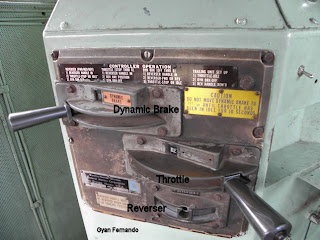
| Control levers on Class M2c No 626 Montreal |
The
main three controls are the Reverser, the Throttle and the Dynamic Brake lever
or Selector
 |
| The Reverser |
The
Reverser
This
is the lowermost of the three controls. Although traditionally referred to as the
“Reverser”, this lever has three positions: Forward, Reverse and Neutral, with
Neutral being the middle position.
The
Reverser handle is removable and the driver (engineer) is expected to remove it
whenever he leaves the cab.
The
Throttle
 |
| The Throttle |
The
Throttle lever is placed above the Reverser and has nine positions if the “Idle”
position is included or eight driving positions otherwise.
Each
position is known as a “notch” and the lever is advanced through the notches in
a stepped fashion (i.e. not in a smooth fashion.)
The
engineer has to advance the throttle one notch at a time to prevent strain on
the engine and possible ensuing damage. For example, he cannot move the handle
from notch one to four without going through notches two and three.
Putting
the throttle into Notch 1 engages a set of contactors (massive electrical
relays). These contactors link the main generator to the traction motors. Each
notch engages a different combination of contactors, producing different
amperages.
The traction motors produce more tractive power at higher amperages.
Some
combinations of contactors put certain parts of the generator winding into a
series configuration that results in a higher amperage. Others put certain
parts in parallel, resulting in a lower output.
The Diesel
engine also needs to “rev up” with each notch and this is achieved by means of
further relays that adjust the fuel injectors.
The
Selector
This
is the topmost handle and movement of this selects either the throttle or the
dynamic brake, with the position being indicated in the selector window. When
the selector is in the “Throttle Position”, advancing the throttle causes power
to be applied and the locomotive moves off.
When
the selector is in the “Dynamic Brake” position, advancing the Throttle lever
increases dynamic braking effort.
This
type of selector arrangement is seen in Class M2 (GM EMD G12) locomotives, whereas
in the Class M6 Henschel locomotives the arrangement is slightly different.
 |
| Control levers on a Class M6 Henschel locomotive |
Differences in the Class M6 Controls
The
Class M6 controls consist of the Reverser and the Throttle as above, but
instead of a Selector, the topmost lever is the Dynamic Brake handle.
Advancing
this handle, results in the dynamic brake effort increasing. It cannot however
be advanced unless the Throttle is in the “idle” position.
Interlocking
The
various levers are interconnected by an interlocking mechanism which prevents
inappropriate use of controls.
For
example, the Reverser cannot be moved when the locomotive is moving under power. To move the Reverser the Throttle has to be moved to "Idle" first.
With dynamic braking, the throttle has to be brought to the idle position before the Dynamic Brake lever can be moved.
With dynamic braking, the throttle has to be brought to the idle position before the Dynamic Brake lever can be moved.
As
mentioned above, in the case of the dynamic brake, the lever cannot be advanced
when the locomotive is under power. In addition there is also a need to wait 10
seconds in idle throttle setting before applying the dynamic brake. This latter warning is
clearly displayed on the control panel.
Other
controls
Other
significant controls on the control panel itself are the Alerter and the Sander
control. The brakes are separately located.
 |
| Control Panel on GM EMD G12 Class M2c Montreal |
 | ||||
| The Author at the controls of Class M6 No 797 |
A note about the photographs: For obvious reasons none of the photos above show the Reverser handle in situ. The Engineers, quite prudently, removed it before I entered the cab!
Picture credits: The photographs all belong to the author. The two line drawings are from the EMD Engine Manuals and are copyright free.
References:
1 HowStuffWorks "How Diesel Locomotives Work":
http://science.howstuffworks.com/transport/engines-equipment/diesel-locomotive10.htm
2 EMD GP-9 operation: Although this deals with the GP-9,
the controls are similar. The
Unofficial CQPA Web Site // EMD GP-9 Operators Manual
3 EMD engine manuals:
http://gelwood.railfan.net/manual/567C-emm.pdf

great work. gave me lot of knowledge. thank you
ReplyDeleteThis is great Gayan. Very informative indeed. What about the Brush built M7s, with their EMD engines, do they have similar controls?
ReplyDeleteI need to check on that. Will do that soon.
Delete